PureData IMU
Summary
A system that allows one to graph the acceleration and angular velocity of a small widget in real-time, wirelessly.
Features:
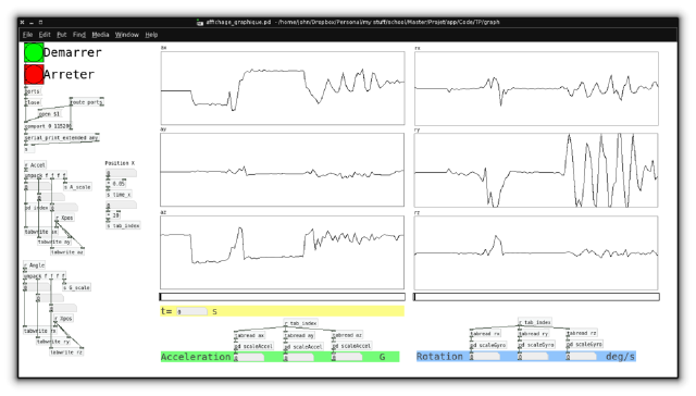
- PC display programmed in Pure Data (a graphical language similar to MAX/MSP)
- Microcontroller: Arduino pro mini
- Wireless: nRF24L01+
- LiPo battery charger & lipo battery for the sensor board
Downloads:
Story
In my master’s first year, I was asked by a professor if I could create an introduction to inertial sensors lab for masters students (in another school). If I accepted it would be counted as that year’s project.
The teacher wanted a wireless system, with a graphical display on a PC.
So I took the challenge, and started developing the system, with my teammate developing the course theory/math questions.
Since I was studying in France, all the course material is in french obviously.
Design
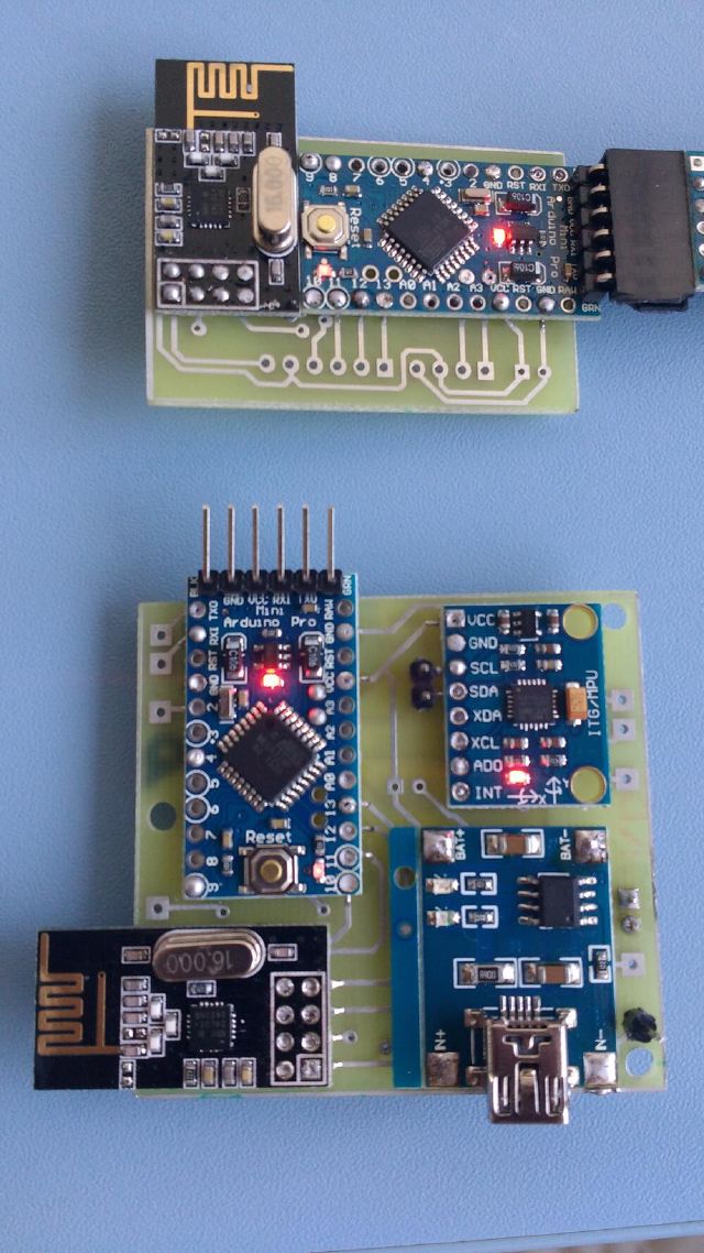
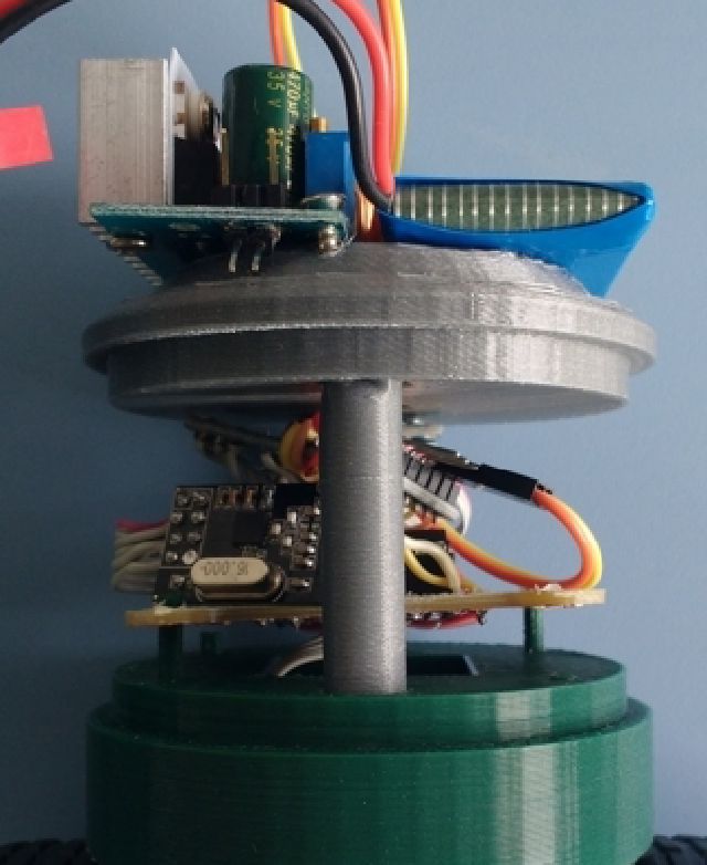
Inertial motion is measured by an IMU on-a-chip, the Invensense MPU-6050, encoded by an atmega328p (3.3V/8MHz), and sent via an nRF24 transceiver.
It is then received by another nRF24 transceiver, decoded by another atmega328p, and sent to the PC via a FTDI cable.
The data is then decoded, recorded, and displayed by the PureData GUI (that you can see at the top of this page).
On the bottom is the sensor module, and top is the receiver module:
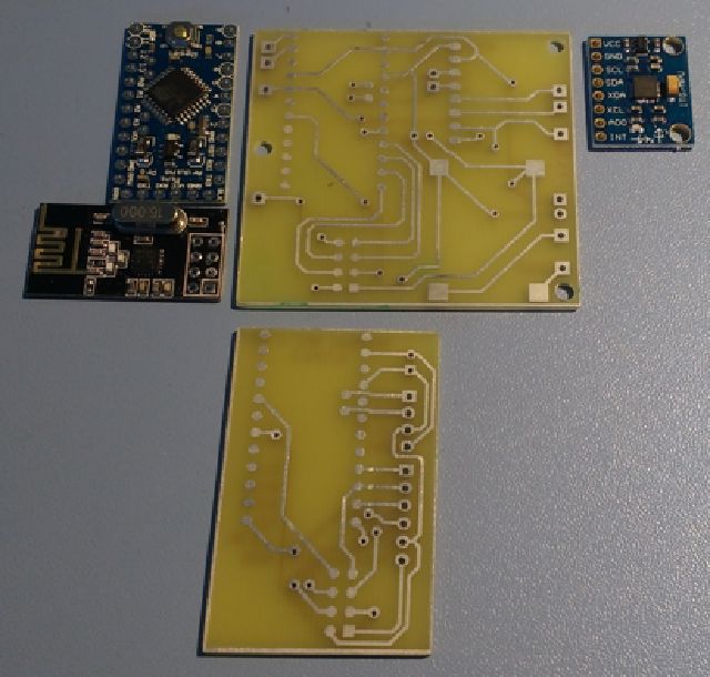
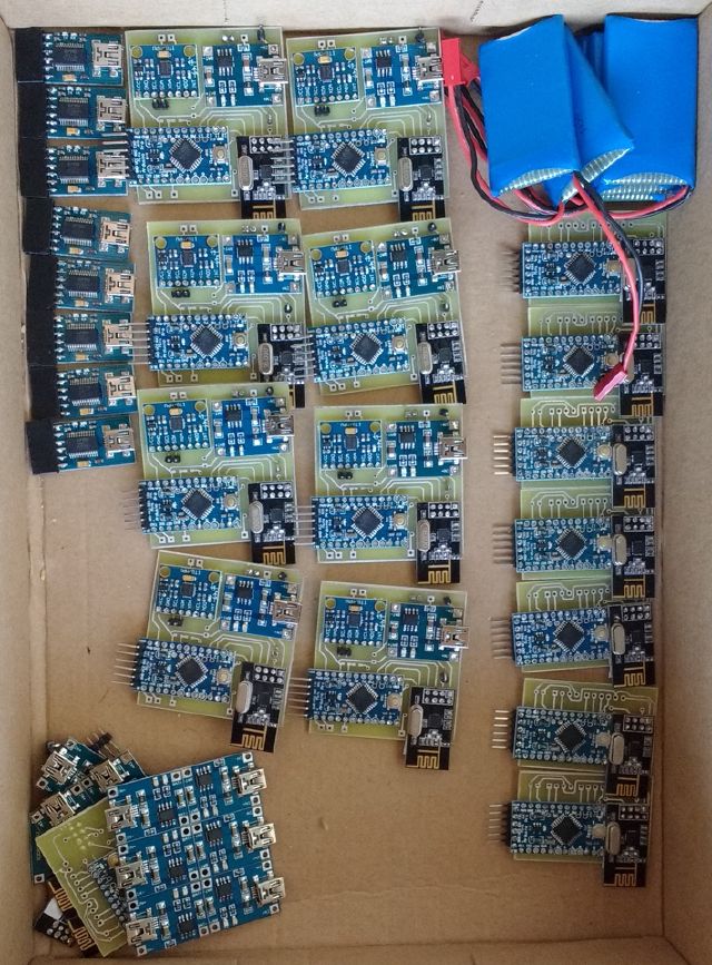
I had to solder 10 of them:
Demo
Superoctagon
For fun, I tried to code a game using Processing.
It is a poor man’s clone of SuperHexagon, but with 8 sides, hence the name.
- Control the ball/player by tilting the sensor board left to right
- The harder the player tilts the board, the faster the walls approach
- Levels are easy to create, just an array of bytes representing each successive walls (1-> wall section present)
You have to install processing and either build the sensor+receiver pcbs or spoof the binary message format with an arduino: the code used for the receiver is in code/imu_gm_rx/.
The processing sketch is in hex/.
I don’t have the hardware anymore, but have a screenshot:
Balance bot
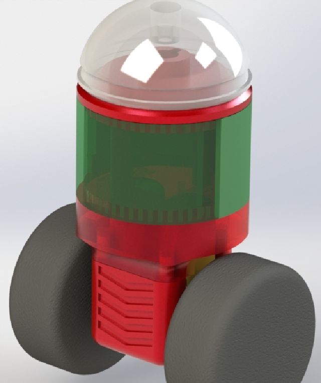
I had a few days left, so I tried to make a balancing robot. I managed to design the parts in solidworks, print them and get a robot rolling. I don’t even have the code anymore, but it was using a kalman filter with accel & gyro data, and a badly-tuned PID.
I had fun designing it though :)
